- 您现在的位置:买卖IC网 > Sheet目录866 > LMZ14203EXTTZE/NOPB (National Semiconductor)IC BUCK SYNC ADJ 3A TO-PMOD-7
�� �
�
�LMZ14203EXT�
�SNVS666F� –� JUNE� 2010� –� REVISED� OCTOBER� 2013�
�www.ti.com�
�If� R� ON� calculated� in� Equation� 8� is� less� than� the� minimum� value� determined� in� Equation� 11� a� lower� frequency�
�should� be� selected.� Alternatively,� V� IN(MAX)� can� also� be� limited� in� order� to� keep� the� frequency� unchanged.�
�Additionally� note,� the� minimum� off-time� of� 260� ns� limits� the� maximum� duty� ratio.� Larger� R� ON� (lower� F� SW� )� should�
�be� selected� in� any� application� requiring� large� duty� ratio.�
�Discontinuous� Conduction� and� Continuous� Conduction� Modes�
�At� light� load� the� regulator� will� operate� in� discontinuous� conduction� mode� (DCM).� With� load� currents� above� the�
�critical� conduction� point,� it� will� operate� in� continuous� conduction� mode� (CCM).� When� operating� in� DCM� the�
�switching� cycle� begins� at� zero� amps� inductor� current;� increases� up� to� a� peak� value,� and� then� recedes� back� to�
�zero� before� the� end� of� the� off-time.� Note� that� during� the� period� of� time� that� inductor� current� is� zero,� all� load�
�current� is� supplied� by� the� output� capacitor.� The� next� on-time� period� starts� when� the� voltage� on� the� at� the� FB� pin�
�falls� below� the� internal� reference.� The� switching� frequency� is� lower� in� DCM� and� varies� more� with� load� current� as�
�compared� to� CCM.� Conversion� efficiency� in� DCM� is� maintained� since� conduction� and� switching� losses� are�
�reduced� with� the� smaller� load� and� lower� switching� frequency.� Operating� frequency� in� DCM� can� be� calculated� as�
�follows:�
�f� SW(DCM)� ?� V� O� *(V� IN� -1)*6.8� μ� H*1.18*10� 20� *I� O� /(V� IN� –V� O� )*R� ON2�
�(12)�
�In� CCM,� current� flows� through� the� inductor� through� the� entire� switching� cycle� and� never� falls� to� zero� during� the�
�off-time.� The� switching� frequency� remains� relatively� constant� with� load� current� and� line� voltage� variations.� The�
�CCM� operating� frequency� can� be� calculated� using� Equation� 7� above.�
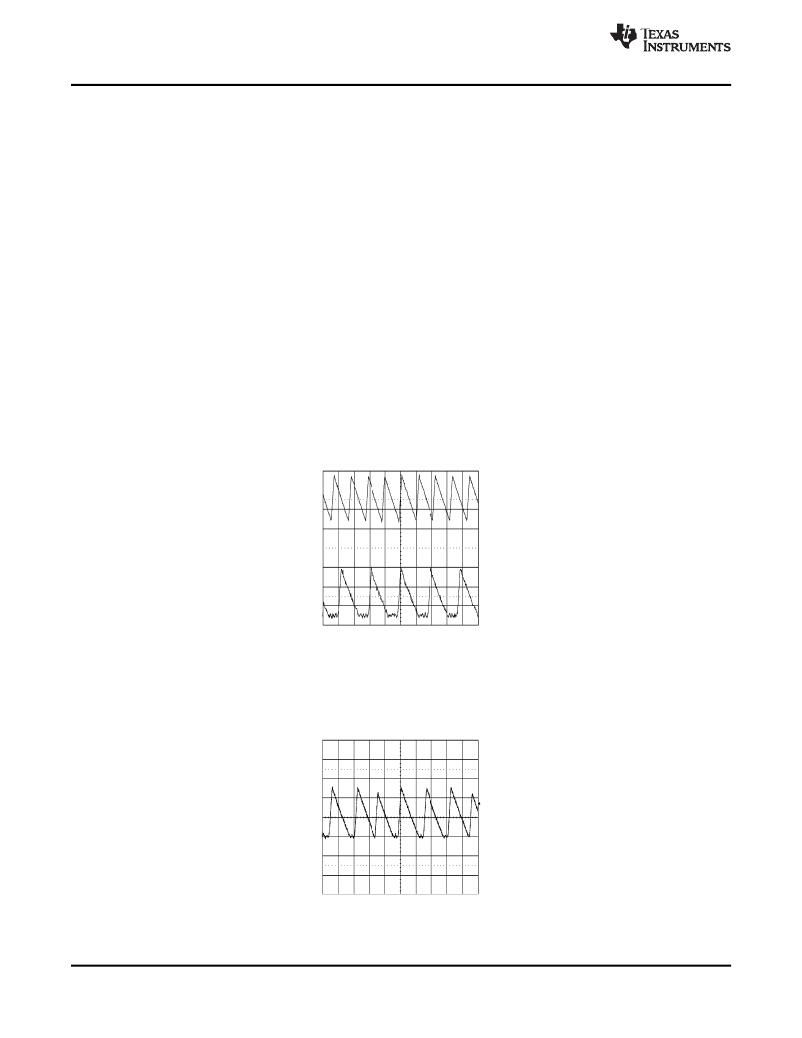
�Following� is� a� comparison� pair� of� waveforms� of� the� showing� both� CCM� (upper)� and� DCM� operating� modes.�
�Figure� 29.� CCM� and� DCM� Operating� Modes�
�V� IN� =� 24V,� V� O� =� 3.3V,� I� O� =� 3A/0.4A� 2� μ� sec/div�
�The� approximate� formula� for� determining� the� DCM/CCM� boundary� is� as� follows:�
�I� DCB� ?� V� O� *(V� IN� –V� O� )/(2*6.8� μ� H*f� SW(CCM)� *V� IN� )�
�(13)�
�Following� is� a� typical� waveform� showing� the� boundary� condition.�
�Figure� 30.� Transition� Mode� Operation�
�V� IN� =� 24V,� V� O� =� 3.3V,� I� O� =� 0.5� A� 2� μ� sec/div�
�The� inductor� internal� to� the� module� is� 6.8� μ� H.� This� value� was� chosen� as� a� good� balance� between� low� and� high�
�input� voltage� applications.� The� main� parameter� affected� by� the� inductor� is� the� amplitude� of� the� inductor� ripple�
�current� (I� LR� ).� I� LR� can� be� calculated� with:�
�14�
�Submit� Documentation� Feedback�
�Product� Folder� Links:� LMZ14203EXT�
�Copyright� ?� 2010–2013,� Texas� Instruments� Incorporated�
�发布紧急采购,3分钟左右您将得到回复。
相关PDF资料
LNC2W153MSEJ
CAP ALUM 15000UF 450V 20% SCREW
LNK2H822MSEJ
CAP ALUM 8200UF 500V 20% SCREW
LNT2H103MSEJ
CAP ALUM 10000UF 500V 20% SCREW
LNX2J562MSEK
CAP ALUM 5600UF 630V 20% SCREW
LNY2W153MSEJ
CAP ALUM 15000UF 450V 20% SCREW
LP122M250H9P3
CAP ALUM 1200UF 250V 20% SNAP
LPW332M2AP45V-W
CAP ALUM 3300UF 100V 20% SNAP
LPX222M200H9P3
CAP ALUM 2200UF 200V 20% SNAP
相关代理商/技术参数
LMZ14203EXTTZNOPB
制造商:National Semiconductor 功能描述:Simple Switcher Power Module 7-Pin TO-PMOD T/R
LMZ14203EXTTZX/NOPB
功能描述:直流/直流开关转换器
RoHS:否 制造商:STMicroelectronics 最大输入电压:4.5 V 开关频率:1.5 MHz 输出电压:4.6 V 输出电流:250 mA 输出端数量:2 最大工作温度:+ 85 C 安装风格:SMD/SMT
LMZ14203H
制造商:NSC 制造商全称:National Semiconductor 功能描述:Evaluation Board modules for high output voltage are easy-to-use DC-DC
LMZ14203H_1106
制造商:NSC 制造商全称:National Semiconductor 功能描述:3A SIMPLE SWITCHER? Power Module for High Output Voltage
LMZ14203HEVAL/NOPB
功能描述:电源管理IC开发工具 LMZ14203H EVAL BOARD
RoHS:否 制造商:Maxim Integrated 产品:Evaluation Kits 类型:Battery Management 工具用于评估:MAX17710GB 输入电压: 输出电压:1.8 V
LMZ14203HTZ
制造商:Texas Instruments 功能描述:POWER MODULE, 42V, 3A, 7TOPMOD 制造商:Texas Instruments 功能描述:POWER MODULE, 42V, 3A, 7TOPMOD; Primary Input Voltage:42V; No. of Outputs:1; Output Voltage:30V; Output Current:3A; Voltage Regulator Case Style:TO-PMOD; No. of Pins:7; Operating Temperature Min:-40C; Operating Temperature ;RoHS Compliant: Yes
LMZ14203HTZ/NOPB
功能描述:直流/直流开关转换器 42V,3A PWR MODULE
RoHS:否 制造商:STMicroelectronics 最大输入电压:4.5 V 开关频率:1.5 MHz 输出电压:4.6 V 输出电流:250 mA 输出端数量:2 最大工作温度:+ 85 C 安装风格:SMD/SMT
LMZ14203HTZE
制造商:NSC 制造商全称:National Semiconductor 功能描述:3A SIMPLE SWITCHER Power Module for High Output